Friday, November 23, 2012

Anti-Gravity Patent Available For Development

U.S. Patent : # 7,663,281
Inventors : Jeffrey J. Nau


invention uses
patent drawings
contact info
patent attorney
http://www.invention.net/nau.htm patent drawing


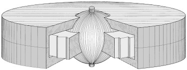
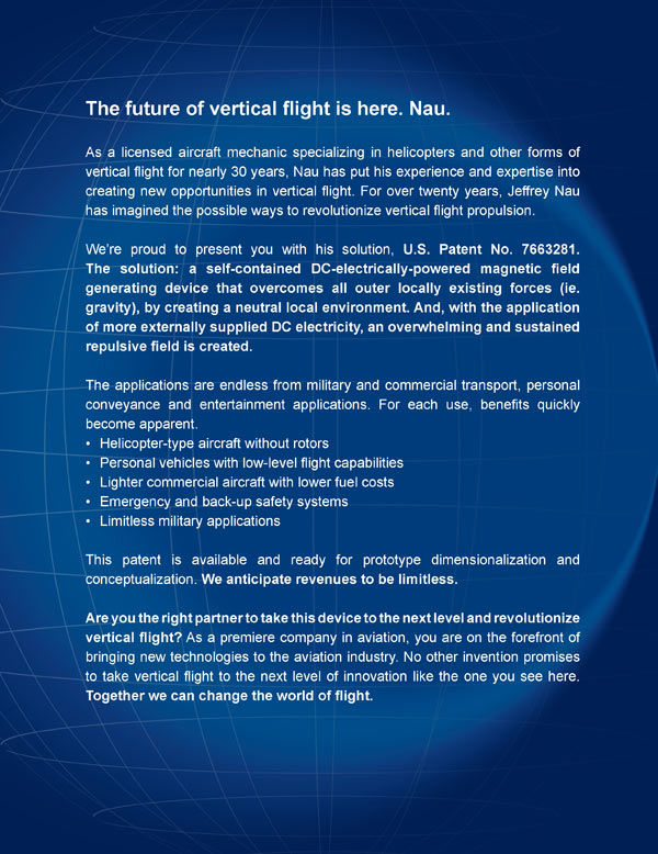
As attorney for the inventor of the innovative Gravity-Opposing Repulsion Generator we are currently seeking manufacturing companies to license, purchase patent rights or enter into a royalty agreement for this timely invention. Interested parties can reach the attorney at the contact numbers listed at the bottom of this page.


Gravity Opposing Repulsion Generator
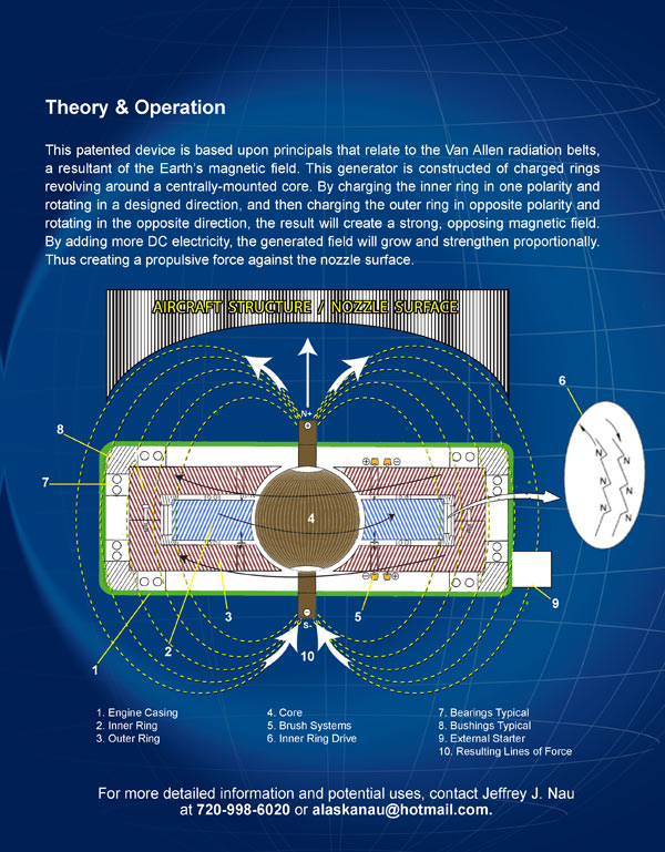
Objects of the present invention:

  • to provide a gravity-opposing repulsion generator utilizing electro-magnetic forces to provide repulsion by creating an electro-magnetic field superior to all surrounding forces

  • to provide a gravity-opposing repulsion generator wherein a pair of electro magnetic rings are disposed one within the other and encircling a central sphere that is electrically energized to opposing polarities to force the counter-rotational movement thereof

  • to provide a gravity-opposing repulsion generator wherein the rotational speed of the rings and the voltage applied thereto increases to a point to effectively achieve gravitational neutrality

  • to provide a gravity-opposing repulsion generator wherein the rotational speed of the rings and the voltage applied thereto are further increased to a point to provide repulsion from the Earth's gravitational field by taking advantage of the north-to-north magnetic situation created by the electro-magnetic field created by the present invention

  • to provide a gravity-opposing repulsion generator having a central sphere comprising a combination of metal conductive material with dielectric material and having a conducting mounting rod forming a core extending vertically from opposing ends thereof

The following pictures are meant to display possible physical characteristics of the present invention and are not to be taken in a limiting sense. It is understood that other embodiments may be utilized and that structural changes may be made without departing from the scope of the invention.

LIST OF REFERENCE NUMERALS
10 present invention 36 inner ring device
12 central sphere38 interface area
14 inner ring 40 lower half of 16
16 outer ring42 upper half of 16
18 dielectric material 44 outer ring bolt
20 conductive material46 bearings
22 conductive mounting rod 48 dielectric support
24 outer face of 1450 rotation of 16
26 inner face of 16 52 rotation of 14
28 north magnet of 1454 mechanical gear mesh
30 north magnet of 16 56 electrical contact brush
32 starter motor58 thermal control means
34 housing 60 capillary tubing
PATENT DRAWINGS
patent drawing
FIGURE 1Figure 1 is a cut-away perspective view of the present invention having a solid conductive sphere.
patent drawing
FIGURE 2Figure 2 is a cut-away perspective view of the present invention having a sphere of conductive metal with interdisposed dielectric material.
patent drawing
FIGURE 3Figure 3 is a cut-away perspective view of the inner ring face.
patent drawing
FIGURE 4Figure 4 is a side view of the core surface of the present invention.
patent drawing
FIGURE 5Figure 5 is a top sectional view of the core face of the present invention.
patent drawing
FIGURE 6Figure 6 is an alternate side view of the core face of the present invention.
patent drawing
FIGURE 7Figure 7 is a sectional side view of the assembly of the present invention.
patent drawing
FIGURE 8Figure 8 is a general side view of the assembly of the present invention.
patent drawing
FIGURE 9Figure 9 is a general side view of the invention.
patent drawing
FIGURE 10Figure 10 is a partial side view of an alternate assembly of the Gravity-Opposing Repulsion Generator.
patent drawing
FIGURE 11Figure 11 is an illustrated view of the induced magnetic field provided by the present invention.
patent drawing
FIGURE 12Figure 12 is a top view of the inner ring drive of the present invention.
patent drawing
FIGURE 13Figure 13 is a top view of the inner ring drive of the present invention.

If you are interested in licensing, purchasing the rights to the above invention or entering into a royalty agreement please contact the office of Michael I. Kroll as follows:
Michael I. Kroll
80 Skyline Drive, Suite 304
Plainview, New York 11803
Tel. #: 800-367-7774
Tel. #: 516-367-7777
Fax #: 800-367-7999
Fax #: 516-802-0510

E-Mail patent@invention.net

No comments:

Post a Comment