In some ways, the Navy's latest computers fall short of the power of 1930s tech.
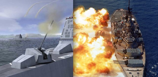
The Advanced Gun System, left, is intended
to take on the role of the battleship's 16-inch guns, right. Aside from
its GPS-guided shell, the digital technology of the AGS's fire control
system does exactly what the USS Iowa's Rangekeeper Mark 8 did—just with
fewer people and less weight.
US Navy
Those projectiles use GPS and inertial guidance to improve the gun’s accuracy to a 50 meter (164 feet) circle of probable error—meaning that half of its GPS-guided shells will fall within that distance from the target. But take away the fancy GPS shells, and the AGS and its digital fire control system are no more accurate than mechanical analog technology that is nearly a century old.
We're talking about electro-mechanical analog fire control computers like the Ford Instruments Mark 1A Fire Control Computer and Mark 8 Rangekeeper. These machines solved 20-plus variable calculus problems in real-time, constantly, long before digital computers got their sea legs. They were still in use when I served aboard the USS Iowa in the late 1980s.
There were a few efforts to marry these older systems to or replace them with digital technology during my tour, one of which (called the Advanced Gun Weapon System Technology Program) was remarkably like the AGS’s 100-mile shell: a GPS and inertially guided 11-inch dart-shaped shell wrapped in a 16-inch peel-away jacket, or sabot, that would have been able to fly nearly as far without the rocket assist thanks to the battleship’s big guns.
So why did the Navy never follow through with digitizing the battleship’s big guns? I asked retired Navy Captain David Boslaugh, former director of the Navy Tactical Embedded Computer Program Office, that question. And if anyone would know, it's Boslaugh. He played a role in the development of the Navy Tactical Data System—the forerunner to today’s Aegis systems, the mother of all digital sensor and fire control systems.
“At one time, my office was asked to do a study regarding upgrading the Iowa-class battleship fire control systems from analog to digital computers,” Boslaugh replied. “We found that digitizing the computer would improve neither the reliability nor the accuracy of the system and recommended, ‘Don't bother.’” Even without digital computers, the Iowa could fire 2,700-pound “dumb” shells nearly 30 miles inland with deadly accuracy, within a circle of probable error of around 80 meters. Some of its shells had circles of destruction larger than that.
Just how can a box of gears, cams, racks, and pins handle ballistics calculations based on differential equations with dozens of variables in real time? How does it manage to put a hunk of metal weighing as much as a Volkswagen Beetle on top of a target over the horizon in the first place? And how did this metal and grease out-calculate digital systems for so long? Let's start with a little bit of a history on battleship ballistics—complete with vintage Navy training films to show precisely how mechanical analog computing works.
Going ballistic
Shooting things with a gun from a ship is not exactly easy. In addition to the usual problems faced by ballistics—calculating how much bang to apply, how high to aim to reach a target at a certain range, how much to compensate for wind and the Coriolis effect—you have to take into account the fact that you’re shooting from a platform that has constantly changing pitch, yaw, and position. If you’re lucky enough to have a stationary target, the variables are still comparable to trying to hit something with a water balloon from the back of a hopping kangaroo.Shooting things within sight of a ship is a feedback loop. Aim at the target, calculate its relative movement and other ballistic conditions, shoot, watch where the shot falls, and adjust. Shooting targets over the horizon is even trickier. It requires a forward observer who can give a precise geographic fix and then give corrections based on where shells land to walk them onto target.
In the days before turrets, ships fired guns in broadsides. Adjustments were generally made by where the shells fell and by waiting to fire until the side facing the enemy was on the upward side of a roll. But with the arrival of dreadnoughts and battle cruisers at the beginning of the 20th century, the range and lethality of ships’ guns both rose dramatically. There was now a greater need for accuracy, too.
That need corresponded with the rise of analog computers. Mechanical analog computers were used by astronomers for centuries to predict star positions, eclipses, and the phases of the moon—the earliest known mechanical analog computer, called the Antikythera Mechanism, dated to 100 BC. But nobody got around to using computers to try to kill people until much later.
Analog computers use a common set of mechanical devices to do their calculations—the same sorts of devices that convert the torque created by a car’s engine into turning wheels, lifting valves, and moving pistons. Data is “entered” into analog computers continuously, usually by the rotation of shaft inputs. A mathematical value is assigned to one full 360-degree rotation of the shaft.
In the days of the ancient Greeks, data entry was performed by turning a wheel. In more modern analog computers, variables from sensor data such as speed, direction, wind speed, and other factors were passed by electromechanical connections—synchro signals from gyrocompasses and gyroscopic “stable verticals,” tracking systems, and speed sensors. Constants, like passing time, were input by special constant-speed electrical motors.
Connecting all the shafts together to turn them into a continuous set of calculation outputs is a collection of gears, cams, racks, pins, and other mechanical elements that translate motion into math through geometric and trigonometric principles. This is also done through “hard-coded” functions that store the results of more complex calculations in their precisely machined shapes. Working together, these parts instantaneously calculate a very precise answer to a very specific set of questions: where will the target be when the giant bullet I push out of a 68-foot long rifled barrel gets there, and where do I need to aim to get it there?
When assembled precisely, analog computers can be much more accurate than digital computers on these types of questions. Because they use physical rather than digital inputs and outputs, they can represent curves and other geometric elements of calculations with an infinite level of resolution (though the precision of those calculations is based on how well their parts are machined, and loss from friction and slippage). There are no least significant digits dropped, and answers are continuous rather than dependent on “for-next” clock-driven computing cycles.
Gear ratios—the use of two gears with circumferences that are a fixed multiple or fraction of each other—are the most basic way to do math with machines. They can be used to scale input or output up or down or to apply constant multiples of an input to another calculation. Turn a shaft geared to another with a 2-to-1 ratio, for example, and the shaft getting the output rotates half as many times.
Rack-and-pinion systems like those used in steering your car are also used in analog computers to translate rotational motion to a linear output—moving a readout or positioning components to solve other sorts of calculations in the ballistics problem geometrically.
You can get an idea of how these sorts of gear-based systems work in analog computers in this clip from a 1953 Navy training film on fire control computers:

Shafts and gears in a fire control computer.

Differential gears, as used in an analog computer.

Cams, the stored functions of analog computing.
First fully developed by Prof. James Thompson of Belfast in 1876, the integrator was further refined by his brother Lord Kelvin as the element of a “harmonic analyzer.”
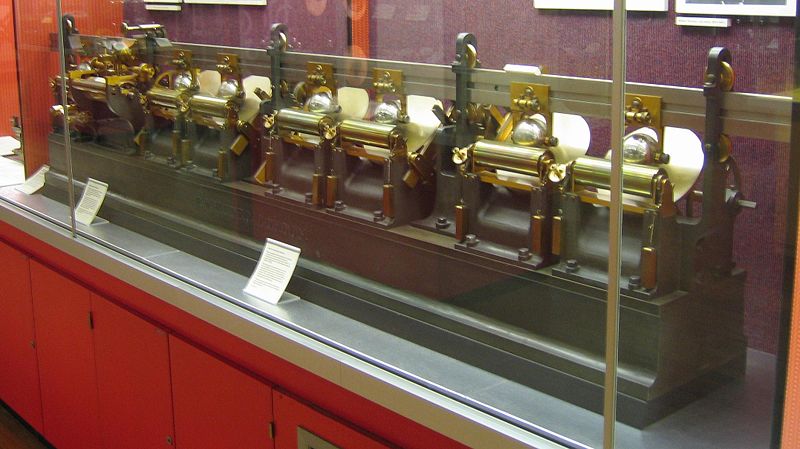
Enlarge / Lord Kelvin's "harmonic analyzer," with disk integrators.
Aside from refinements to make it more reliable under the demanding conditions of shipboard operation, the integrators in fire control computers in operation through the 1990s were essentially the same as those used by Lord Kelvin in function, as shown in the video below. Hannibal Ford, the man who designed the Rangekeeper and Mark 1 fire control computers, invented this improved integrator, which uses a pair of balls in a carriage to transmit rotation information from the turning disc.

A
disc-type integrator, as used in the Mark 1 Fire Control Computer, is
similar in design and function to Lord Kelvin's integrator.
The network is the (fire control) computer
The fire control “systems” of the First World War were largely standalone pieces connected by people shouting over phones and voice tubes. The only data that came into the Rangekeeper Mark I automatically was the ship’s course, thanks to a gyrocompass repeater. That would change over the next decade as the navies of the world got more comfortable with this newfangled thing called electricity.The Washington Naval Treaty of 1922 ratcheted back naval development for nearly a decade, but Ford continued the development of the Rangekeeper through the '20s, culminating in 1930 with the Rangekeeper Mark 8. The Mark 8 would be the zenith of big naval gun fire control. It was the system used aboard Iowa-class battleships to direct the ships’ 16-inch guns, and it calculated every broadside from the four ships since their commissioning in World War II until their bombardment of Iraqi troops in the Gulf War in February of 1991.
Enlarge /
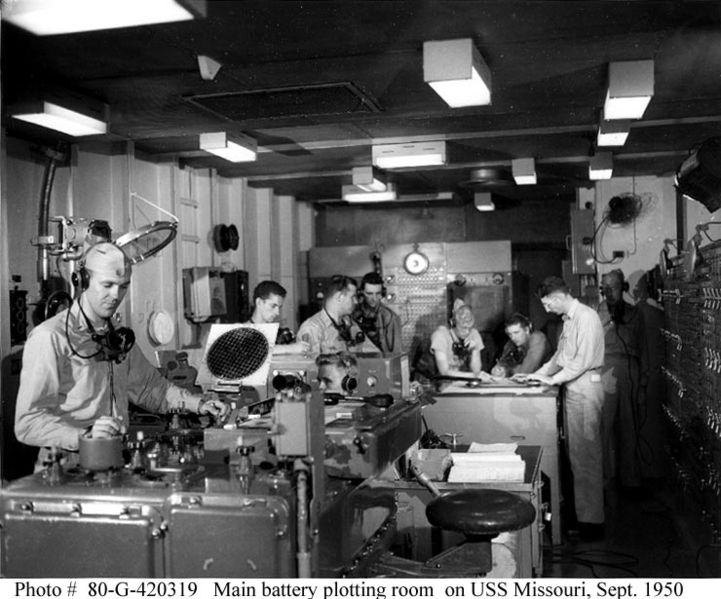
The Main Battery Plot room aboard the USS Missouri, where the
Rangekeeper Mark 8 and its associated analog computing hardware was
tended to. The switchboards on the wall controlled which turrets and
guns were under the system's control.
Once the system was “locked” on a target, the Mark 8 would send signals through a switchboard to the gun turrets and mounts to keep them aimed properly, next sending stabilizing data to adjust the elevation of the guns for the ship’s yaw and pitch. The Mark 8 was itself electromechanically networked. It consisted of five boxes of analog computing hardware bolted together into a single unit.
The Mark 8 was for the big guns, which were strictly for surface targets because of their size and rate of fire. Smaller guns, like the 5-inch 38 caliber dual-gun mounts on the Iowa and many of the other smaller warships of the World War II era, needed to be able to target faster, smaller targets in three dimensions—plainly speaking, airplanes. This required much more complex calculations, leading to the pinnacle of electromechanical analog computing: the Ford Instruments Mark 1 Fire Control computer.

The Mark 1A Fire Control Computer—3,000 pounds of aluminum alloy computing power.
The computer took into account parallax between the director and the guns it was controlling. It also had to calculate fuse times for mechanical fuses to ensure that the shell would explode near the target. (That said, there were a few times in gunnery practice in the 1980s when the Iowa directly hit a towed aerial target, albeit not on purpose.)
Considered to be the most accurate anti-aircraft computer in service during the war, the Mark 1 still had some serious limitations. It depended on mechanical fuses to explode shells near airborne targets, and it could only handle calculations on aerial targets moving at less than 400 knots relative horizontal and 250 knots relative vertical speed. That made it ineffective against jets and kamikaze attacks.

Enlarge /
The Mark 48 "shore attack" computer, an electrical analog system with
electromechanical inputs. It had a light table for charts that projected
position and target data from below.
And while they’re generally reliable, their greatest enemies are friction and mechanical fatigue. Keeping a fire control computer properly lubricated and watching for gear wear is a bit more of a chore than dropping by the local garage for an oil change. Then there’s the issue of “reprogramming” an analog computer. If you want to change the range of inputs they handle or modify the output to account for new variables, that requires the equivalent of a transmission rebuild.
For most applications that analog computers were built for, that wasn’t a problem. The variables of fire control were pretty well set for most of the last century. The arrival of jet aircraft and the need to handle more long-range bombardment of land targets led to a new round of innovations in analog systems that lasted through the mid-1970s: electrical analog systems.
These electronic computing systems weren’t digital, and they performed the same sorts of functions as gears and cams with analog electronic components. But the electronic parts were lighter and easier to maintain than full-on mechanical systems, and they could integrate with mechanical systems through signal outputs similar to the synchros used to integrate other sensors.
During World War II, Bell Labs developed the first all-electronic fire control computer, the Bell Mark 8. While it never saw service, parts of the technology were married with an upgrade for the Ford Mark 1, designated the Mark 1A. The improved system helped track and target faster aircraft.
The Mark 1A and the Rangekeeper Mark 8 also got some extra electrical help for land targets during the Korean War. The Mark 48 “shore attack” computer was designed specifically to handle “indirect fire”—shooting at things that the ship couldn’t see based on information from a spotter plane, a forward observer, or (starting in the late 1980s) a Pioneer drone. It used the existing director system to point at a known reference point, typically a geographic feature identified on a chart. It could also use radio or satellite navigation signals to fix the ship’s position. The Mark 48 then calculated the fire control solution based on the fix and the location provided for the target, pushing the data over to the Rangekeeper or Mark 1A, depending on which guns were being used to bombard the unfortunate target at the other end.
Legacy systems
The four Iowa-class battleships were the only ships ever to get the Mark 48. For the rest of the fleet, the switch to digital fire control systems started in the mid-1970s, as ship designs moved toward being lighter and more focused on hunting submarines and aircraft than on shooting other ships..

The
author as a young Navy officer aboard the USS Iowa in 1988, just
outside the armored citadel on the bridge that sat below the director
for the fire control system the Rangekeeper Mark 8 was part of.
During my time aboard, we fired more shells from the ship’s 16-inch guns than Iowa fired in the entire Korean War. And despite all the experiments in adding digital technology to the gun system, one simple sensor installed just before my arrival made the guns more accurate than they ever had been before——a Doppler radar sensor that could detect shell velocity as it left the barrel.
The radar was installed after the USS New Jersey had been rushed back into service in the early 1980s, and it experienced major problems with the accuracy of its guns during the Beirut crisis. The problems were largely due to the fact that the bags of gunpowder used aboard the ship had been re-mixed and its explosive profile had changed.
By accurately measuring the gun’s muzzle velocity on the first shot with a particular lot of gunpowder bags, the fire control crew could get an idea of what it would be for other shots and change the velocity input for the computer accordingly. I saw that accuracy firsthand aboard Iowa on a couple of occasions, including a one-night gunfire exercise off the coast of Vieques, Puerto Rico. Using inert training rounds, the gunners hit a metal target dead-on, and I could see the sparks fly from the collision from several miles away.
The final testament of the battleships’ accuracy came during the Gulf War, when the USS Missouri and USS Wisconsin used Pioneer drones as spotters to attack Iraqi artillery batteries and bunkers. It was after a bombardment by the Missouri that Iraqi troops on Faylaka Island surrendered to a drone off the Wisconsin, associating the drone’s low pass with another imminent bombardment.
The real end of analog fire control came not because of accuracy, but simply because of dollars and cents. The Navy could crew 10 USS Zumwalts with what it took to put the Iowa to sea, and it could fuel twice as many with what it took to top off the battleship’s tanks. The Navy spent much of the 1980s and 1990s trying to justify keeping the battleships in service despite their cost, attempting to use things like the Advanced Gun Weapon System Technology Program or using the spaces for testing higher-powered gunpowder loads. The 1989 explosion aboard the Iowa—possibly caused by spontaneous combustion of the gunpowder milled in the 1930s—put an end to that experimentation.
Ironically, analog computing technology lives on aboard the Zumwalt as part of its fire control system. Electronic analog computers are part of the phased-array radar system that aims Zumwalt’s missiles. Still, in the eyes of older Navy vets, it’s not really a fire control computer unless it has servos.
No comments:
Post a Comment